Seeding Laser Source
The SPARC_LAB seed laser source consist mainly in a laser amplification chain operating in parallel to the photo-injector laser system, a transport line devoted to set the pulse shape, focalization and intensity of the laser pulse, a chamber devoted to the generation of high harmonics in gas (HHG), which has been realized at CEA, and an system to inject the seed pulse in the electron beam line.
Different wavelengths are available as seed sources.
- The main IR laser source at 800 nm.
- A non-linear Barium-Borate crystal (BBO) is used to produce the second harmonic at 400 nm with an energy 150 μJ per pulse.
- A High Harmonics Generated in gas (HHG) source is given by an Argon gas cell located in dedicated vacuum chambers where the infrared laser is focused, the generation of odd nonlinear harmonics occurs up to the 7th order (266, 160, and 114 nm).
The general layout is described in Fig. 1

Figure 1: Block diagram of the seeding system
Laser system
The laser system consists of a Ti:Sa Legend-HFE regenerative amplifier, provided by Coherent, pumped by an Evolution 30 and seeded by a Mira laser oscillator (the same laser which drives the photoinjector). The system provides an energy up tp 2.5 mJ at 800 nm with a pulse length of 120 fs (FWHM) and a line bandwidth of 8 nm (FWHM) at the Fourier limit.
The laser is installed in a clean room in a stabilized optical table. An infrared optical transfer line 15 m long has been installed to transport the Mira seed pulse from the photocathode laser hall to the seeding laser room (see Fig.2).
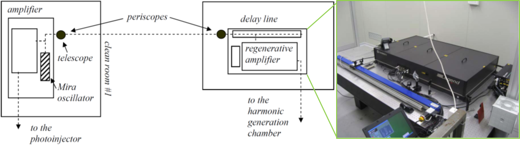
Figure 2: Layout of the laser system for the seeding experiment. The regenerative amplifier installed in the SPARC clean room. On the left the delay line for the synchronization with the e-beam is visible
Laser transport stage
The seed-laser pulse is transported and manipulated before injection in the undulator. A telescope and a plano-convex lens (f=2 m) allow to focus the beam inside the gas cell for the HHG.
Control of IR laser intensity is realized in two steps, where a half-wave plate changes the polarization of the light, and a polarizing splitting cube selects the component with desired polarization. The two steps allow to vary the laser pulse energy, down to few nJ, and eventually the polarization by rotating the two wave plates.
At the end, a linear movable stage allows to select a linear filter to further attenuate the laser if IR is used as direct seed or let it pass through (by removing the filter) if the IR is used to generate harmonics. The stage host also the BBO crystal for the second harmonic generation.
The interaction of the seed with electrons requires a linear horizontal polarization (undulators are horizontally polarized and so is the produced FEL radiation). The output polarization of the seed pulse, after the transport line, is different depending on which of different source type is used (direct IR or up-converted in non-linear medium, due to phase matching). For these reasons a third wave plate is installed before the linear stage to give the possibility of switching between horizontal and vertical polarization of the seed pulse to restore the right one before injecting the laser in the electron beam line.
Figure 3: Scheme of the transport layout of the seed laser form the Legend amplifier to the entrance of the HHG chamber. HWP half wave plate, SPC splitting polarizer cube, LSF linear stage filter, BBO second harmonic nonlinear crystal, H and V indicates the polarization Horizontal or Vertical of the IR pulse in different position of the transport line
Harmonic generation chamber
When the HHG source is used, the laser is delivered, through an antireflecting coated 790 nm window, in a first chamber where harmonic generation occurs through interaction of the laser with Argon in a gas cell. The gas inlet valve is triggered at 10 Hz (same rep-rate of electron beam). A second chamber is used to increase the vacuum gradient between the first chamber and the SPARC_LAB transfer line. Then a third chamber, 1.5 meters downwards, is used to match the harmonic beam (used also for other seed types) to the undulator by means of two spherical mirrors. A view of the setup of the three chambers is shown in Fig.4
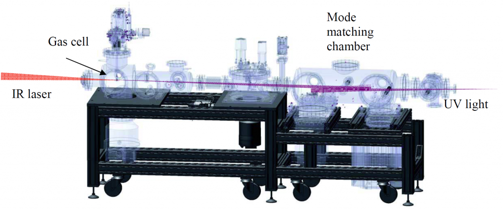
Figure 4: Layout of the harmonic generation chamber
The chamber has been operating until summer 2019. More recently the HHG chamber has been removed from the seeding line and a new optical setup to focus and match the seed in the undulator is under development.
Injection periscope
After the mode shaping and focalization, the seed is injected in the FEL line by means of a periscope with piezo-controlled mirrors for adjusting the transverse overlap of the seed pulse with electrons. The periscope is constituted by two chambers (installed in the middle of the transfer line) containing piezo-controlled mirror holders.
A magnetic chicane with small dipoles has been inserted in the layout of the transfer line in order to allow the electron beam to perform a small orbit deviation and avoid interaction with the upper mirror of the periscope when inserted.
The electrons-seed temporal overlap is ensured by an optical delay line located in the LEGEND-HFE room. A fast photodiode at the end of the undulator chain is used to monitoring the temporal electrons-seed synchronization just looking at the signals of seed laser respect to the SASE FEL radiation signal (observed by suppressing the seed).
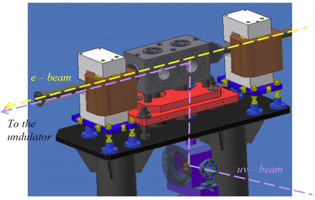
Figure 5: CAD representation of the injection chicane and periscope
Publication highlights:
- “Commissioning of the laser system for the seeding experiment at SPARC”, C. Vicario et al., EUROFEL-Report-2007-DS4-093 (2007)
- “Commissioning of the HHG source at SPARC”, M. Labat et al., EUROFEL-Report-2007-DS4-094 (2007)
- “Implementing a HHG Laser as seed in a HGHG-FEL”, L. Giannessi et al., EUROFEL-Report-2007-DS4-098 (2007)
Seeding experiments