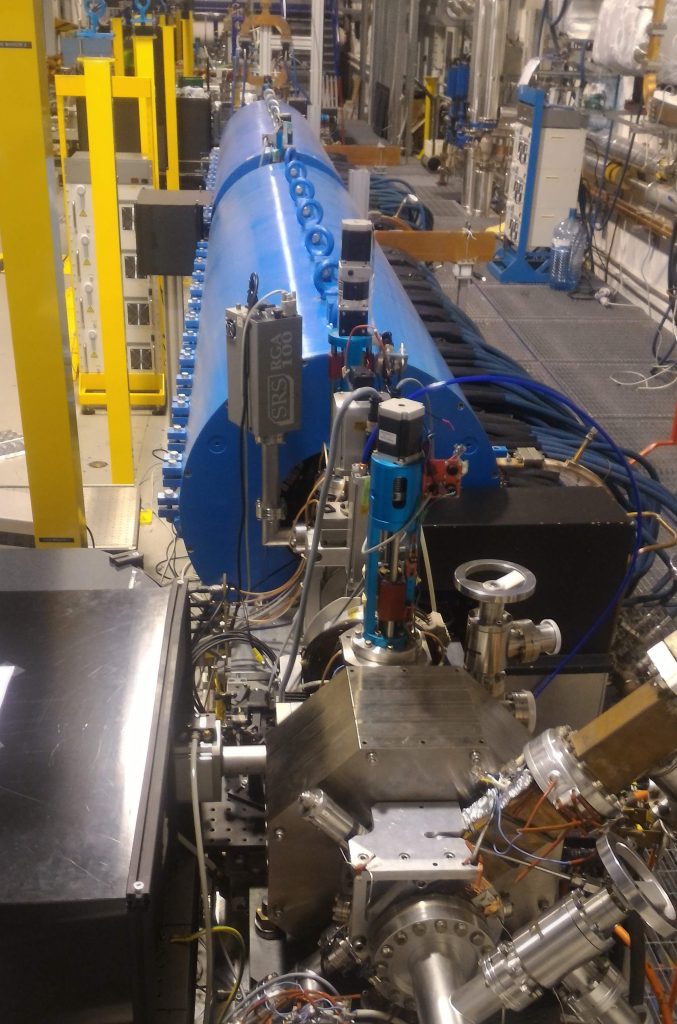
Gun and S-band sections
The SPARC_LAB photoinjector is based on a 1.6 cell S-band (2.856 GHz) RF gun which operates at high gradient, 120 MV/m peak on cathode. The electron beam is focused by a solenoid just after the gun and it enters the RF linac structures. The entrance of the first accelerating section is placed at 1.5 meters from the cathode, where the local maximum of transverse emittance oscillations coinciding with a beam waist was measured.
RF structures are used to accelerate the beam having the particles standing on the crest of the wave (like a surfer on the sea) where the beam has the maximum energy gain from the RF. Higher gradient give more energy per meter of accelerating section, up to the limit of the vacuum breakdown that produce a discharge inside the structure. SPARC_LAB started operating with 3 SLAC-type traveling wave (TW) high gradient (22 MV/m) S-band sections reaching about 180 MeV of energy at the end of the linac. More recently we have replaced one S-band section with a C-band section (at 5.712 GHz) that allows an higher gradient (>40 MV/m), so in half the previously space we have the new linac section and the remaining space is occupied by the experimental chamber for plasma acceleration.
Velocity bunching: longitudinal beam profile measured as a function of the injection phase delay
We also developed a technique that uses the RF structure also to compress the beam, called Velocity Bunching. If a low energy beam (3-5 MeV) is injected in a TW accelerating cavity close to the zero-crossing phase (no acceleration), it accumulates RF-induced correlated velocity spread that tends to compress the beam (give higher velocities to the slower trailing particles); at the same time the bunch slips back to accelerating phases. Differently from the ballistic bunching, acceleration and compression take place simultaneously. The key point for beam compression is represented by the difference between the wave phase velocity and the beam mean velocity.
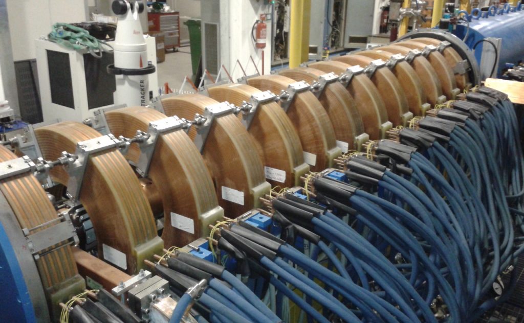
Two long solenoids have been placed around the first two linac sections to prevent beam blow up during compression. Each solenoid is composed by a long iron joke containing 13 coils forming a long solenoidal magnetic field. The coils are grouped in triplets which can be separately powered (except for the first coil which has a stand-alone power supply needed for fine field adjustments). With this flexibility the amplitude of the magnetic field on axis can be shaped longitudinally to optimize the beam envelope along the linac.
Having two or more bunches at picosecond or less temporal separation can be very useful for many applications, like plasma acceleration or two color FEL.
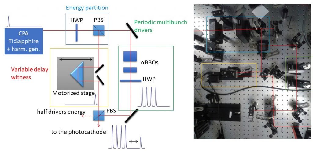
Concept and realization of a laser comb with split and delay and birefringent crystals
In this injector operating mode, the photocathode is illuminated by a comb-like laser pulse in order to produce a train of sub-picosecond high-charge density pulses within the same RF gun accelerating bucket. The required laser pulse shape is characterized by two or more short pulses spaced by a few picoseconds. One technique used for this purpose relies on a birefringent crystal, where the input pulse is decomposed in two orthogonally polarized pulses with a time separation proportional to the crystal length. The crystal is $\alpha$-cut beta barium borate (BBO), which is a UV transparent optical material characterized by a strong birefringence. By rotating the crystal, thus the orientation of the fast and slow axis, respect to the laser polarization it is possible to chose the ratio between the laser pulses intensities. Another technique involves the use of a split and delay lines with polarizing beamsplitter and remote controlled delay lines, that allow a fine tuning of the intensity and the separation of the pulses.
Downstream of the gun exit, the work done by the space charge force produces a linear energy chirp along each pulse, which can be exploited to compress the initial charge profile by means of an RF accelerating structure, operating in the velocity bunching mode. The resulting electron pulse trains have some hundreds pC charge, a sub-picosecond length and a repetition rate of some terahertz.
In RF compression, as can be observed in figures below, the initial pulse time profiles shrink when the beam injection phase is off-crest (-80°) and also the pulse inter-distance is reduced. This regime is called under-compression. When the injection phase is around 90°, the two pulses overlap and the highest peak current is reached, obtaining the maximum of the compression. In the over-compression regime (- 93°), the two pulses are again separated and the time order is inverted. The peak current still has a significant enhancement compared with the on-crest distribution (0°). The corresponding rotation in the longitudinal phase space of the beam is clearly visible in the simulations and in the measurements. The trailing pulse experiences a stronger longitudinal focusing than the leading pulse, resulting in an over-compression at the phase (-93°) when the relative position of the two pulses is exchanged.
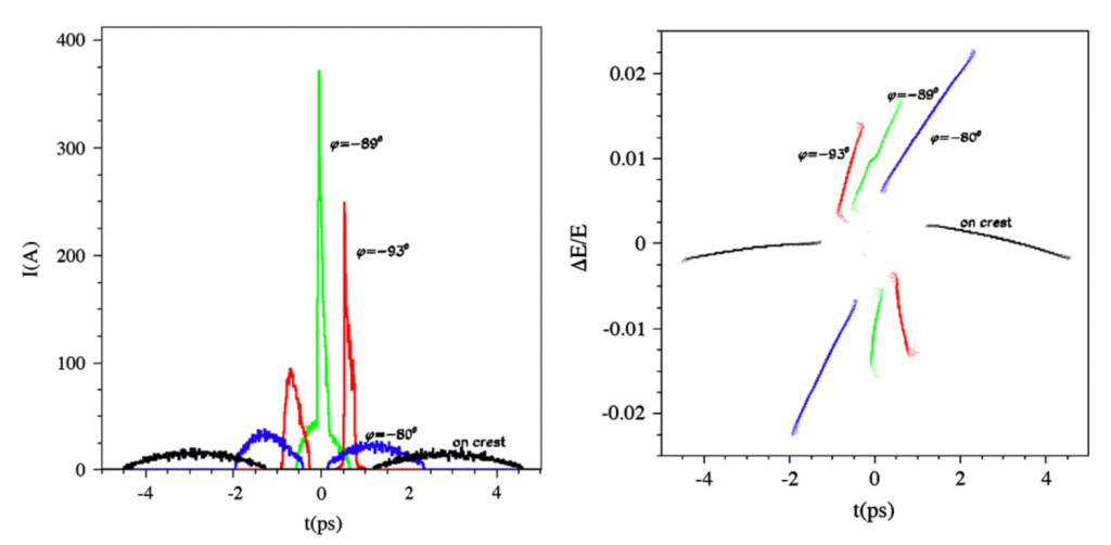
PARMELA simulations: on crest (0°, black line); moderate compression (-80°, blue); maximum compression(-89°, green); and over-compression (-93°, red). On the left the current longitudinal distribution simulations, on the right the longitudinal phase space simulations.
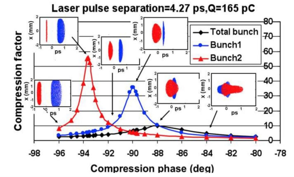
TSTEP simulation showing the compression factor as function of the compression phase, i.e. the RF phase of the first accelerating section, for a two-bunches train with total charge of 165 pC.
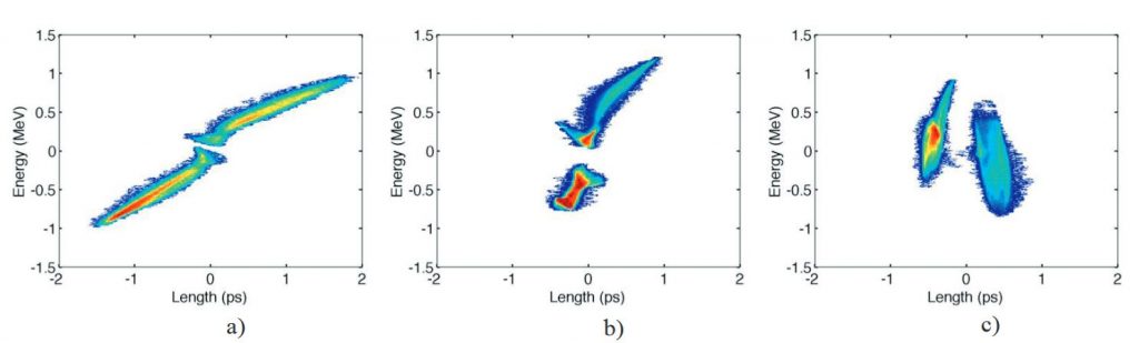
Measured longitudinal phase spaces for undercompression (a), maximum compression (b) and overcompression (c)
Using a combination of birefringent crystals and/or split and delay lines to generate a larger number of comb-like laser pulses we also tested configurations with more than 2 pulses:
More examples of measured comb beams: on top the position in the longitudinal phase space of one of the beam can be widely tuned to be before or after the other one, on bottom different configuration with up to 5 different bunches.
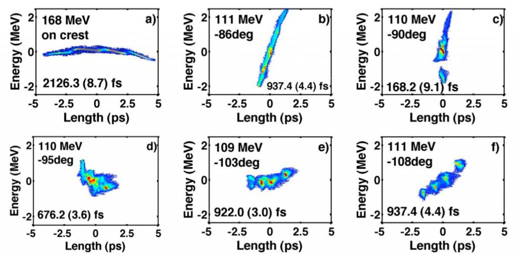
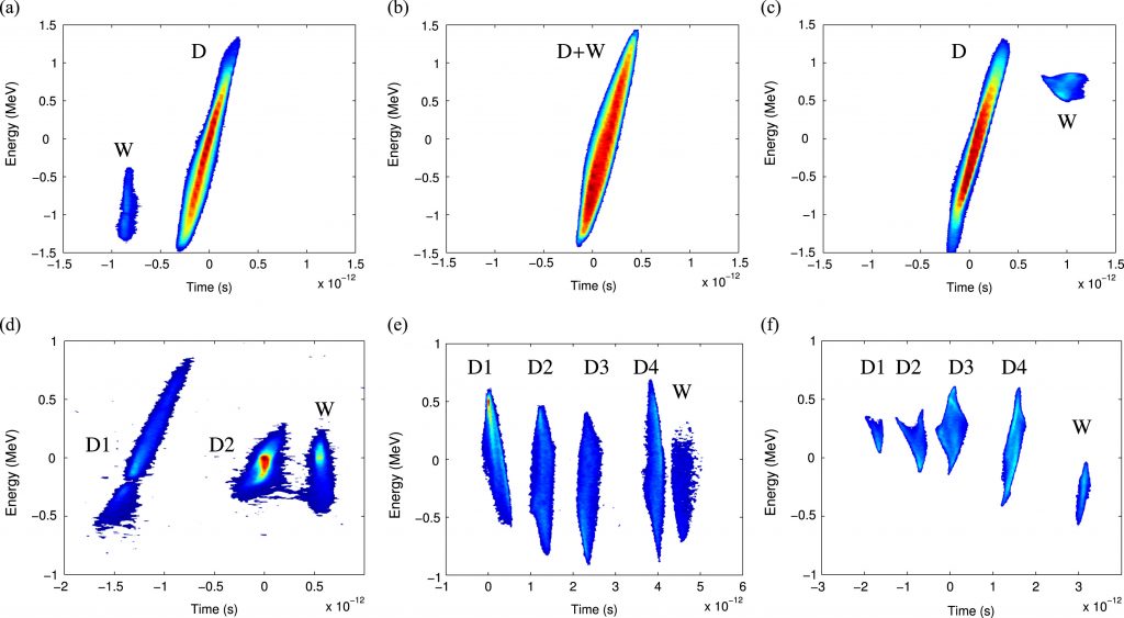
Longitudinal phase spaces for 4 bunches at different compression phases: a) on crest configuration, b) undercompression, c) maximal compression, d)-f) overcompression
Publication highlights:
- “Velocity bunching in photo-injectors”, L. Serafini and M. Ferrario, AIP Conference Proceedings vol. 581 (2001) pag. 87, doi: 10.1063/1.1401564
- “Direct Measurement of the Double Emittance Minimum in the Beam Dynamics of the Sparc High-Brightness Photoinjector”, M. Ferrario et al., Phys. Rev. Lett. vol. 99 (2007) pag. 234801, doi: 10.1103/PhysRevLett.99.234801
- “Experimental Demonstration of Emittance Compensation with Velocity Bunching”, M. Ferrario et al., Phys. Rev. Lett. vol. 104 (2010) pag. 054801, doi: 10.1103/PhysRevLett.104.054801
- “Two Color FEL driven by a Comb-like Electron Beam Distribution”, E. Chiadroni et al., Phys. Procedia vol. 52 (2014) pag. 27, doi: 10.1016/j.phpro.2014.06.006
- “Laser pulse shaping for high gradient accelerators”, F. Villa et al., Nucl. Instr. Meth. Phys. Res. A vol. 829 (2016) pag. 446, doi: 10.1016/j.nima.2016.01.010
- “Beam manipulation with velocity bunching for PWFA applications”, R. Pompili et al., Nucl. Instr. Meth. Phys. Res. A vol. 829 (2016) pag. 17, doi: 10.1016/j.nima.2016.01.061
- “Characterisation and optimisation of a C-band photo-injector for compact light sources”, G. Campri et al., Proceedings of 15th IPAC (2024), pag. WEPC06, doi:10.18429/jacow-ipac2024-wepc06
- “Space Charge Forces analytical model for emittance compensation”, M. Carillo et al., J. Phys.: Conf. Ser., vol. 2687 (2024), pag. 062009 doi: 10.1088/1742-6596/2687/6/062009
Contact person: R. Pompili, riccardo.pompili@lnf.infn.it, Tel. (+39) 069403-2465
Last update: 05/2019