Optical Transition Radiation (OTR) is emitted when a charged particle crosses the boundary between two media with different index of refraction. It is well known since many years, but only in the 90’s received attention as powerful diagnostics tool. We focus here on the incoherent part of the radiation emitted at wavelength shorter than the bunch length. It happens often in the visible range.
When a charged particle passes through the aperture on a boundary between two media with different refraction indices, diffraction radiation (DR) is emitted both into the forward and the backward direction. The DR is emitted only when the dimension of the transverse electromagnetic field, at given wavelength and beam energy, is larger than the aperture size. Since the beam passes through a hole, DR provides a nonintercepting diagnostics tool, and is therefore well suited for measuring parameters of high charge density beams in a parasitic way.
Single Shot emittance
When the space charge contribution is negligible the quadrupole scan is the most used technique to measure the emittance. It is based on the measurement of the beam transverse spot changing the current in one or more quadrupoles. But it is a multi shot measurement and because it uses magnetic lenses, it is very sensitive to energy spread. Unfortunately, up to now there are not reliable and well established single shot measurements of transverse emittance, while several experiments have been already carried out, always with not negligible energy spread.
Using OTR angular distribution is possible to retrieve the total angular divergence of the beam. But even with a concurrent measure of beam size it is not possible to obtain the transverse emittance due to the lack of knowledge of the correlation term.
In our setup the correlation term is measured in every single shot. Our experimental setup is shown in Figure.
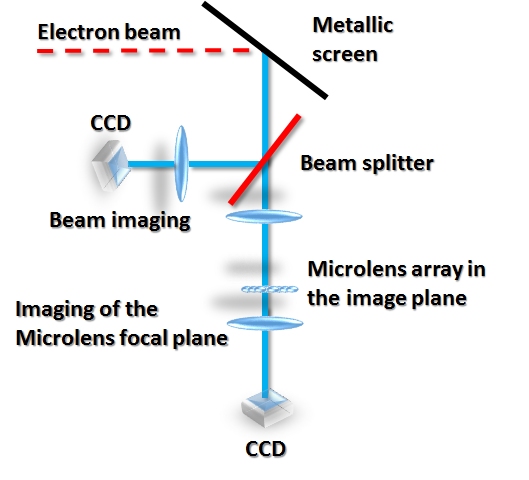
Experimental setup: a replica of the beam is produced in the two arms. In the second one in the image plane there is a microlens array. Their focal plane is imaged in a CCD detector.
The light coming out from a silicon aluminated screen is divided but a 90:10 beam splitter. The 10% is then used to image the beam in a Hamamatsu Orca II camera, high quantum efficiency, equipped with a Nikon f=180 mm focal length F/ 2.8. The other part arrives on a f=400 mm focal length achromatic doublet. In the image plane of such a lens, with a magnification 1:1, is placed a Thorlabs mounted lens array. These are plano-convex lenses, with a pitch of 300 μm, and a focal length of 18.6 mm.
Extensive simulations have been performed in Zemax to understand the effect of possible aberration of such a lens system. A complete virtual measurement has been simulated, starting from the radiation produced by a bunch charge and propagating in the whole optical system. No significant effect of aberration in the microlenses have been found. The focal length of the microlens array is very small, just 18.6 mm, so for geometrical constrains it is impossible to place the detector directly on its focal plane. Instead we put another achromatic lens with focal f=5 cm to image with 1:1 magnification this focal plane into our intensified camera, a Hamamatsu Orca IV.
The experiment has been performed using 200 pC bunch charge at 125 MeV. The maximum energy was limited by the use of only two of the three accelerating sections. The third one was not available due to a severe problem on its klystron. In this energy range the minimum detectable beam divergence is in the order of 0.5 mrad. Even if we have tried to deteriorate the value of the emittance and focus the beam in one dimension in order to push the beam angular spread over this value we did not succeeded.
In Figure is reported a qualitative comparison between a simulated pattern behavior and a real single shot measurement.
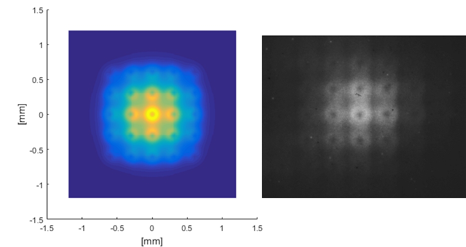
Comparison between a simulation (left) and a first measurement (right).
Every illuminated lens produces its own radiation ring. Analyzing the single OTR angular distribution is possible to retrieve the value of the angular spread. The qualitative agreement between simulation and measure is excellent. We extract from every single ring the profile and we fit them.
As expected the fit is very good but the value of the angular spread is about 500 μrad, totally dominated by the resolution limit at this energy. Further experiments are needed at higher energy.
Publication highlights:
- “Transverse emittance diagnostics for high brightness electron beams.”, A. Cianchi et al., Nucl. Instrum. Meth. in Phys. Res. Section A vol. 865 (2017) pag. 63, doi: 10.1016/j.nima.2016.11.063
- “Recent studies on single-shot diagnostics for plasma accelerators at SPARC_LAB.”, F. G. Bisesto et al., Nucl. Instrum. Meth. in Phys. Res. Section A vol. 909 (2018), pag. 364, doi: 10.1016/j.nima.2018.02.059.
- “Zemax simulations describing collective effects in transition and diffraction radiation.”, F. G. Bisesto et al., Optics express vol. 26 (2018) pag. 5075, doi: 10.1364/OE.26.005075
Not intercepting emittance measurement
In the traditional DR-based diagnostics, the angular distribution of the diffraction radiation, which is emitted when a charged particle beam passes a slit aperture, is detected. For ODRI (Optical Diffraction Radiation Interference) measurements, an additional slit aperture with different size is used.
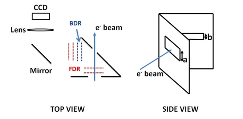
Sketch of the two-slit setup. Dimension a is the aperture size of the first slit; b is the size of the second slit. The FDR produced at the first interface is reflected and interferes with the BDR from the second surface. An optical system, described later in the paper, images the radiation onto a CCD device
The distance between the screens is shorter than the radiation formation length. The ODR emitted in the forward direction at the first slit interferes with the backward radiation produced at the second slit. Different slit apertures are needed in order to avoid signal cancellation due to destructive interference between the emitted fields. The interference pattern contains valuable information regarding the beam parameters: transverse size, angular divergence and relative position inside the slits can be retrieved from it. When using a single slit setup, it is not possible to distinguish the beam size and the beam position inside the slit, and a complementary diagnostic is needed in order to separate these two contributions. This is not the case when using ODRI with non-collinear slits. This is an important difference because in our case we do not need any additional diagnostics to retrieve the beam position inside the slit, and also the contributions to the angular distribution of beam position and beam size are separated from each other.
The measurements were performed at the FLASH free-electron laser user facility at DESY (Hamburg).
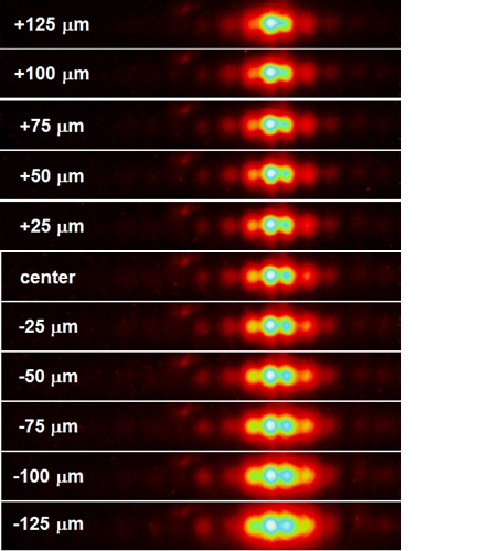
Images of ODRI angular distribution for different positions of the beam with respect to the center of the 0.5 mm slit.
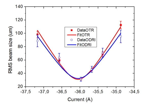
Comparison between quadrupole scans obtained by imaging a single electron bunch using the OTR screen and using the ODRI angular distribution produced by a long train of bunches going through the slits.
In order to validate the ODRI results, the quadrupole scan was also performed using conventional OTR imaging. The resulting emittance is ϵ = (2.3 ± 0.4) mm mrad for the ODRI measurements and ϵ = (2.4 ± 0.4) mm mrad for the OTR measurements. The agreement between the two techniques is excellent, concerning both the measured emittance as well as the shape of the quadrupole scan curve.
Publication highlights:
- “Nonintercepting electron beam size monitor using optical diffraction radiation interference.”, A. Cianchi et al., Physical Review Special Topics-Accelerators and Beams vol. 14 (2011) pag. 102803, doi: 10.1103/PhysRevSTAB.14.102803
- “First non-intercepting emittance measurement by means of optical diffraction radiation interference.”, A. Cianchi et al., New journal of physics vol. 16 (2014) pag. 113029 doi: 10.1088/1367-2630/16/11/113029
Beam diagnostics