Capillary design and discharge simulations
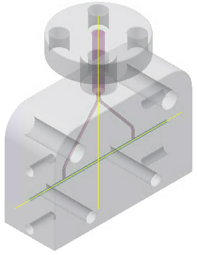
Fig. 1: CAD capillary design: length 3 cm, diameter 500 μm, 2 inlets.
Simulations capable of reproducing the trend of plasma density during and after discharge are essential to understand the plasma stability, therefore the beam-plasma matching. It is important to understand which capillary geometry is most suitable (length, diameter, number of inlets, type of outlet), what discharge intensity to use, what type of gas or gas mixture, and what initial system conditions to set up. In this way, it is also possible to find the right time window for the synchronization process with the beam. The process of producing the capillary (CAD project, 3D printing and possible assembly of components), the construction of the discharge circuit and the installation of the experiment are then based on the simulated results.
Starting from the existing CAD projects (example in Fig. 1) with which the capillaries used in the laboratory are 3D-printed, simulations have been built in OpenFOAM (Open- source Field Operation And Manipulation), a C++ toolbox for the development of customized numerical solvers, and pre-/post-processing utilities for the solution of continuum mechanics problems, most prominently including Computational Fluid Dynamics (CFD). By means of the use of sonicFOAM, a transient solver for trans-sonic/supersonic turbulent flow of a compressible gas, we are able to solve the the Euler partial differential equations (Cauchy equations of conservation of mass and balance of momentum and energy), using both Dirichlet and Neumann boundary conditions, depending on the variables considered. The simulation aim is to obtain the distribution of the density of gas inside and immediately outside the capillary, from the moment in which the gas is injected to the moment in which the discharge begins. In the simulated geometry of the capillary there is an inlet that replicates the electro-valve open for the whole time of the simulation (typically 3 ms), on which a gas pressure (typically helium) in the range between 50 mbar and 1000 mbar is applied. Two outlet zones simulate the vacuum coming out of the capillary. The thermal conductivity condition can be set on the capillary surface, imposing a fixed ambient temperature as a boundary condition in that region (fixed temperature isotherm), while null flow is set on this surface, which means a zero pressure derivate condition.
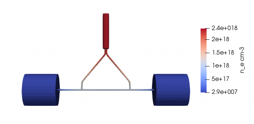
Fig. 2: OpenFoam simulation: gas density $n_e$ after 3 ms, for the capillary presented in the previous figure. The pressure on the inlet is 100 mbar.
For the Courant Friedrichs Lewy (CFL) convergence condition is set a Courant parameter typically in the range 0.01 – 0.1, while the time step of the simulation is variable in the range 10-15 – 10-7 s for each iteration. Using the simulated gas pressure, temperature and velocity variables, it is possible to calculate the gas density for each point at each moment of the simulation. An example of the result of these simulations in OpenFOAM is in Fig. (2), it represents the density $n_e$ at the final time.
After that, the fluid-dynamic simulations of the discharge process and of the evolution of the plasma density are carried out by means of a modified version of PLUTO, an open source Euler magnetohydrodynamic (MHD) code (therefore with a fixed grid).
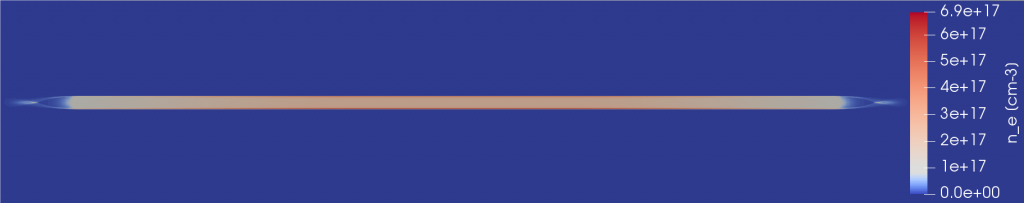
Fig. 3: MHD simulation for a discharge profile with a peak current equal to 250 A and a capillary of the model in the Fig. 2. (a) Plasma density distribution
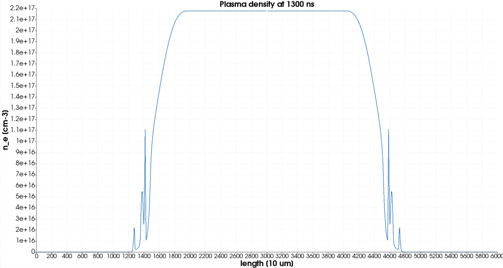
Fig. 3: MHD simulation for a discharge profile with a peak current equal to 250 A and a capillary of the model in the Fig. 2. (b) Longitudinal profile on axis.
Fig. 3: MHD simulation for a discharge profile with a peak current equal to 250 A and a capillary of the model in the Fig. 2. (c) Transverse profile on axis.
The gas discharge process has to be simulated with a fluid model, as a particle in cell approach would be computationally impractical, due to the time scales involved (> 1 μs) and to the spatial resolution required (< 100 μm). In particular, a single-temperature fluid is used. A local thermodynamic equilibrium approximation is taken, which allows for computing the ionization degree at each time step only as a function of the local plasma temperature and mass density. In particular, Saha ionization model is employed. The magnetic skin effect and the influence of Lorentz force on the plasma column are neglected. These simplifications allow to skip the treatment of a self-consistent magnetic field. The plasma is thus modeled with a hydrodynamic system, with the addition of an Ohmic heating term in the energy conservation equation; the current density is computed in a static current flow approximation (for details see Numerical studies on capillary discharges as focusing elements for electron beams, E. Brentegani).
Therefore, the main properties set in the model are:
- axial symmetry;
- fixed mesh (rectangles);
- resolution of MHD equations by means of a temperature curve;
- current imposition instant by instant;
- ionization calculated as an approximation of LTE (local thermal equilibrium) with the Saha equation;
- electrical resistivity and thermal conductivity calculated according to a rigorous process.
The code imports pressure, temperature and speed output data from Open-FOAM simulations at the final time, along with the real current profile of the discharge circuit.
An example of MHD simulation for a discharge profile with peak current equal to 250 A and a capillary of the model in Fig. (1) is reported in Fig. (3): plasma density ne is shown after a time of few hundred of ns after the discharge (a), with the corresponding profiles on the longitudinal and transverse axis (b) and (c). This image shows the presence of plasma plumes coming out of the capillary, as found in the experimental results, and the existence of a time window in which there is uniformity of longitudinal plasma density, required for plasma acceleration experiments, as well as the existence of a hollow transverse profile, suitable for laser guiding experiments.
Plasma simulations
Contact person: G. Costa gemma.costa@lnf.infn.it, tel. (+39) 069403-2934