Working point simulations: EuPRAXIA@SPARC_LAB
The Horizon 2020 Project EuPRAXIA (“European Plasma Research Accelerator with eXcellence In Applications”) is a European project with the target of building a highly compact and cost-effective facility with multi-GeV electron beams using plasma as the acceleration medium. The plasma accelerator has been designed with the target of having a compact facility able to pilot a free electron laser in the range of the soft up to hard X rays, requiring an energy of the electron beam in the range 1 to 5 GeV. The concept design report has already been addressed and involves a site to be located in Frascati (EuPRAXIA@SPARC_LAB) for particle driven plasma wakefield acceleration.
The EuPRAXIA@SPARC_LAB photo-injector is designed in order to provide trains of electron beams with a sufficient degree of control to allow the acceleration of a witness bunch. In the early phase, the photo-injector will operate up to 500 MeV energy and the plasma module will provide the energy doubling required for the soft X-rays. The final goal of 5 GeV bunches will be achieved by means of a train of bunches with an initial energy 1 GeV.
Start to end simulation of the first phase have been successfully addressed. The electron bunch inside the photo-injector is simulated by means of the codes Elegant and T-Step. The bunches phase space has been initialized on Architect code, demonstrating the possibility of using this bunch structure in order to obtain a high quality witness bunch with 1 GeV energy with an effective gradient >1 Gv/m. Afterwards we simulated the transport of the bunch by means of Elegant code and the FEL radiation by means of Genesis code.
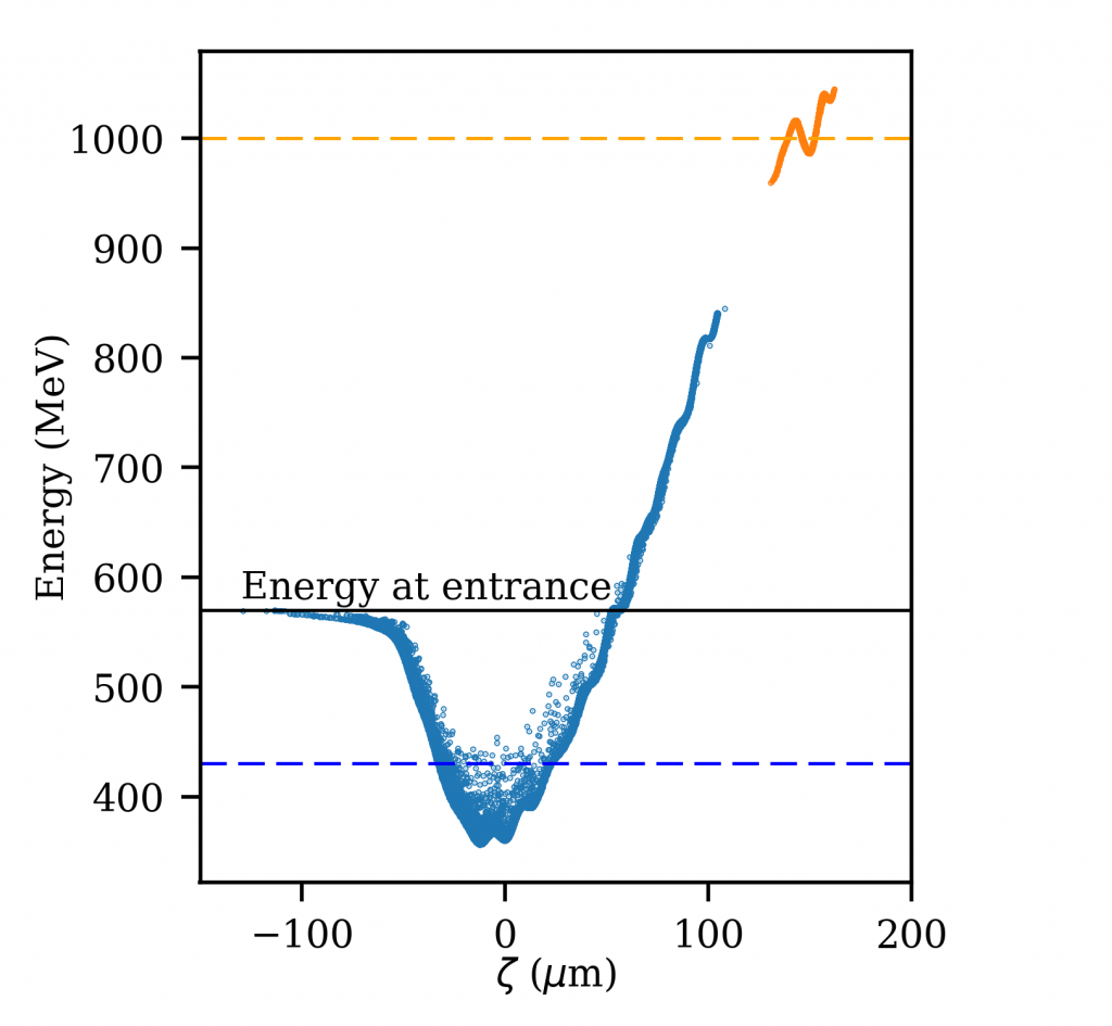
Fig. 1: Longitudinal phase space of the bunches after the acceleration in the 1 GeV EuPRAXIA case.
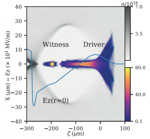
Fig. 2: Density distribution and longitudinal field in the 1 GeV EuPRAXIA case.
The 5 GeV working point preliminary study has been performed by means of a train of four bunches with an energy of 1.2 GeV at the beginning of the plasma module. The structure with three driving bunches is necessary in order to overcome the intrinsic limit of the transformer ratio in the particle driven schemes. Previous considerations in literature state that the ratio between the maximum accelerating field and the maximum decelerating self-field generated by a low density bunch with a symmetric current profile in a plasma cannot exceed a factor 2. That means that in long-range plasma acceleration one can extract an amount energy per particle up to two times the injection energy before the current profile of the driving bunch is severely deformed. A resonant scheme, involving more than one driver, is the strategy that we chose in order to achieve higher energies. The train of bunches with increasing charges properly shaped decreases the decelerating self-field, maintaining slightly unaltered the accelerating field behind the train, overall increasing the transformer ratio up to 7.5. The effective transformer ratio, including the effect of the self-field of the accelerated bunch reduces the transformer ratio to a value of 3.5, allowing increasing the energy up to 4.5 times the initial energy (5.5 GeV). By means of the code Architect we simulated the acceleration of the trailing bunch up to 5 GeV in a 2.4 m long ideal plasma channel. All the drivers have the same parameters, listed below, with increasing charges, properly shaped to obtain inside every bunch a constant maximum decelerating field. Then we inserted and optimized a realistic trailing bunch with high current profile (3 kA) in order to obtain a low energy spread (0.5 %) at the extraction. The transverse matching condition $\sigma_{x,y}=\sqrt[4]\frac{2}{\gamma}\sqrt{\frac{\varepsilon_n}{k_p}}$ has been exploited in order to maintain unaltered the projected emittance at the exit of the plasma channel.
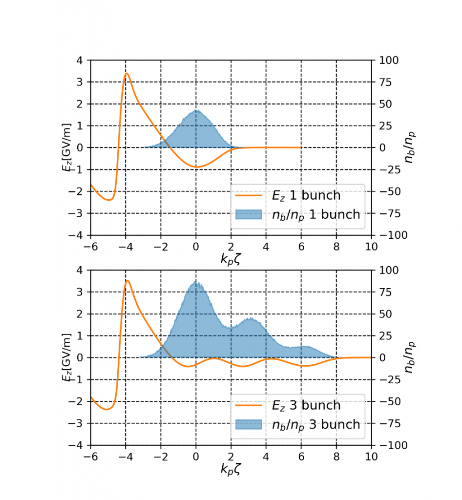
Fig. 3: Comparison between the accelerating fields generated by 1 driver and 3 drivers.
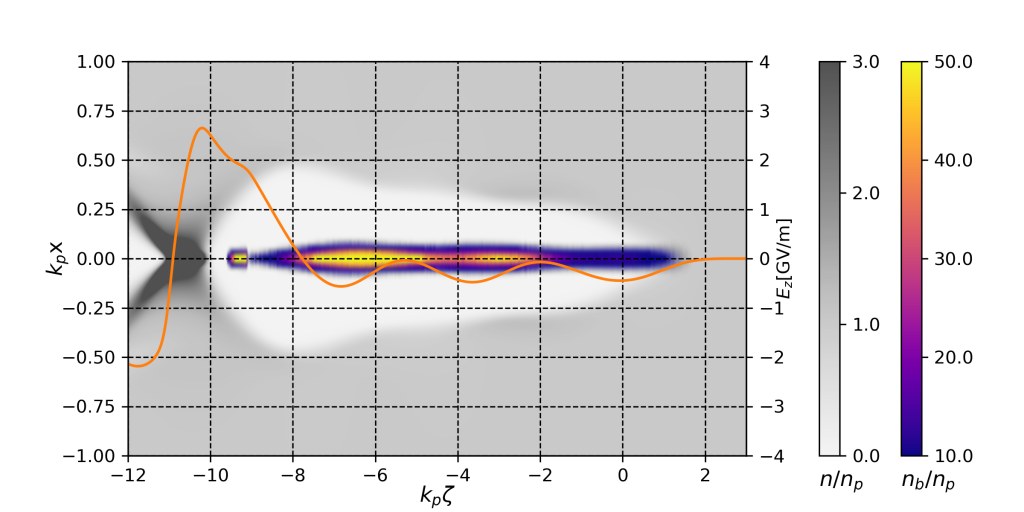
Fig. 4: Density distribution and longitudinal field in the 5 GeV EuPRAXIA case.
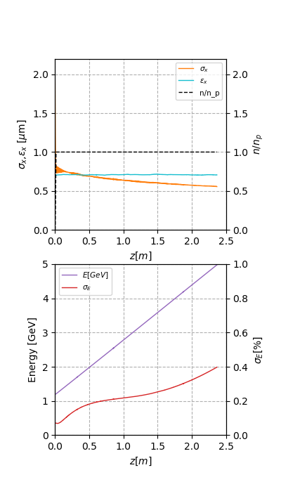
Fig. 5: Integrated parameters evolution for the EuPRAXIA 5 GeV case.
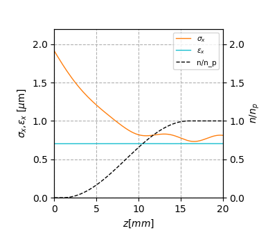
Fig. 6: Injection detail for the EuPRAXIA 5 GeV case.
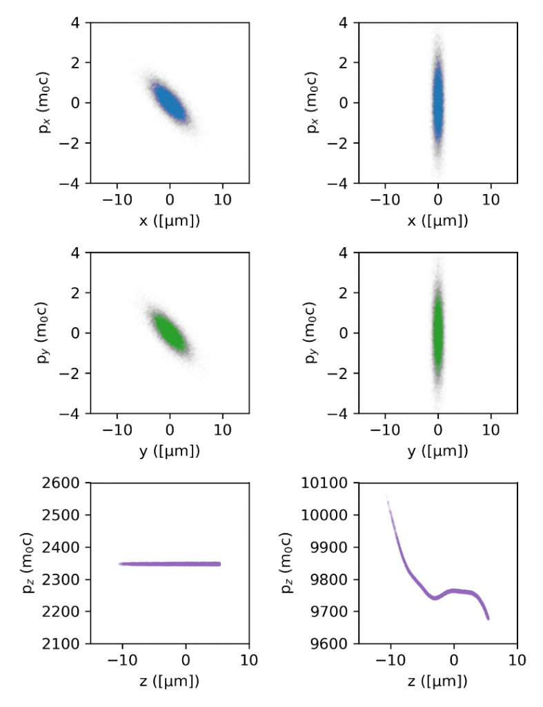
Fig. 7: Witness final phase space for the EuPRAXIA 5 GeV case.
Plasma simulations