Radiofrequency
Radiofrequency
The SPARC_LAB photoinjector was originally conceived to use only the american S-band radiofrequency (2856 MHz) to accelerate the electron bunches. It was composed by a 1.6 cells RF gun (SLAC design), two 3 m long SLAC-type TW high gradient (22 MV/m) accelerating section and one 3 m long low gradient (13 MV/m) section. The total achieved beam energy was around 170 MeV (on crest acceleration).
Recently, the SPARC_LAB test facility developed R&D projects on new acceleration techniques involving plasma acceleration. These experiments foresee a very short electron bunch (or a train of bunches), passing through a plasma filled capillary. Thus, the last low gradient accelerating section has been replaced by one 1.4m C-band (5712MHz) accelerating section and a PWFA interaction chamber (see figure 1).
The design and brazing of the new accelerating structure has been performed at INFN. Due to the higher gradients reached by such structure, the same (or even higher) energy beam can be obtained reducing the linac length. The use of C-band structures for electron acceleration has been adopted in a few FEL linacs in the world, among others, the Japanese Free Electron Laser at SPring-8 and the SwissFEL at Paul Scherrer Institute (PSI). The C-band section is traveling wave, constant impedance structure with symmetric input and output axial couplers. Its design has been optimized for the operation with a SLED RF pulse compressor. The design and realization of a dedicated low level RF system has been done in collaboration with PSI in the framework of the EU TIARA project. Preliminary experimental results appear to confirm the operation of such structures with accelerating gradients larger than 35 MV/m.
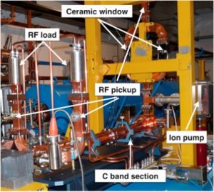
Figure 1. C-band section installed at SPARC_LAB during the high power test
The C-band structure is fed with a 50 MW Toshiba ET37202 klystron. The high voltage pulsed modulator and the 400 W solid state driver amplifier have been manufactured by ScandiNova (Sweden) and Microwave Amplifier (England) respectively. The new system will also include a SKIP-type pulse compressor, developed by the Institute of High Energy Physics (IHEP) of Beijing (China), that is currently under commissioning at LNF. Further details on C-band development at SPARC_LAB are reported here.
Synchronization
Synchronization
Synchronization system task is to establish a fine temporal alignment among all the relevant sub-system oscillators to guarantee a temporal coherence of their outputs with a precision of 10 ps ÷ 10 fs. Usually one stable oscillator is used as master reference. The sub-system slave oscillators are phase locked to the master.
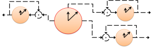
Figure 2. Synchronization system task
In photo-injectors, the general synchronization layout is reported in figure 3. The master oscillator is connected to the machine sub-systems using a signal distribution system. The slave oscillators of each sub-system are then phase locked to the master by a dedicated phase-locked loop (PLL). The design of PPLs changes accordingly with the nature of the master and slave signals. They can be full electrical, opto-electrical or opto-electro-mechanical PLLs. The master oscillator and its distribution system can be electrical or optical, depending on system specifications and on the dimensions of the experimental apparatus.
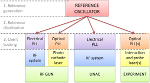
Figure 3. General layout of a synchronization system in photoinjectors
- Electrical signal generation and distribution: the master oscillator in this case is a microwave crystal inside a temperature stabilized oven OXCOs with low phase noise. The sinusoidal signal (typically at the same frequency of the accelerating field) is sent through coaxial cables to the clients. Cables can be actively stabilized, if needed, and their attenuation can be compensated by dedicated RF amplifiers. In any case, for apparatus larger then hundreds of meters, is good rule to use fiber links that offer a simpler mechanical installation and a better system performance in terms of phase noise detection sensitivity and signal attenuation.
- Optical signal generation and distribution: to fulfill the task of an optical master oscillator, a comb fiber laser system with repetition rate around 100 MHz (sub-harmonic of the accelerating radiofrequency) and a pulse duration <200fs is typically used. The laser comb is sent to the client by means of actively length stabilized fiber links to reduce added drifts. Links are also dispersion compensated and can feed an experimental apparatus up to few kilometers distant from the source without degrading the spectral purity of the reference signal. For a more detailed discussion follow this link.
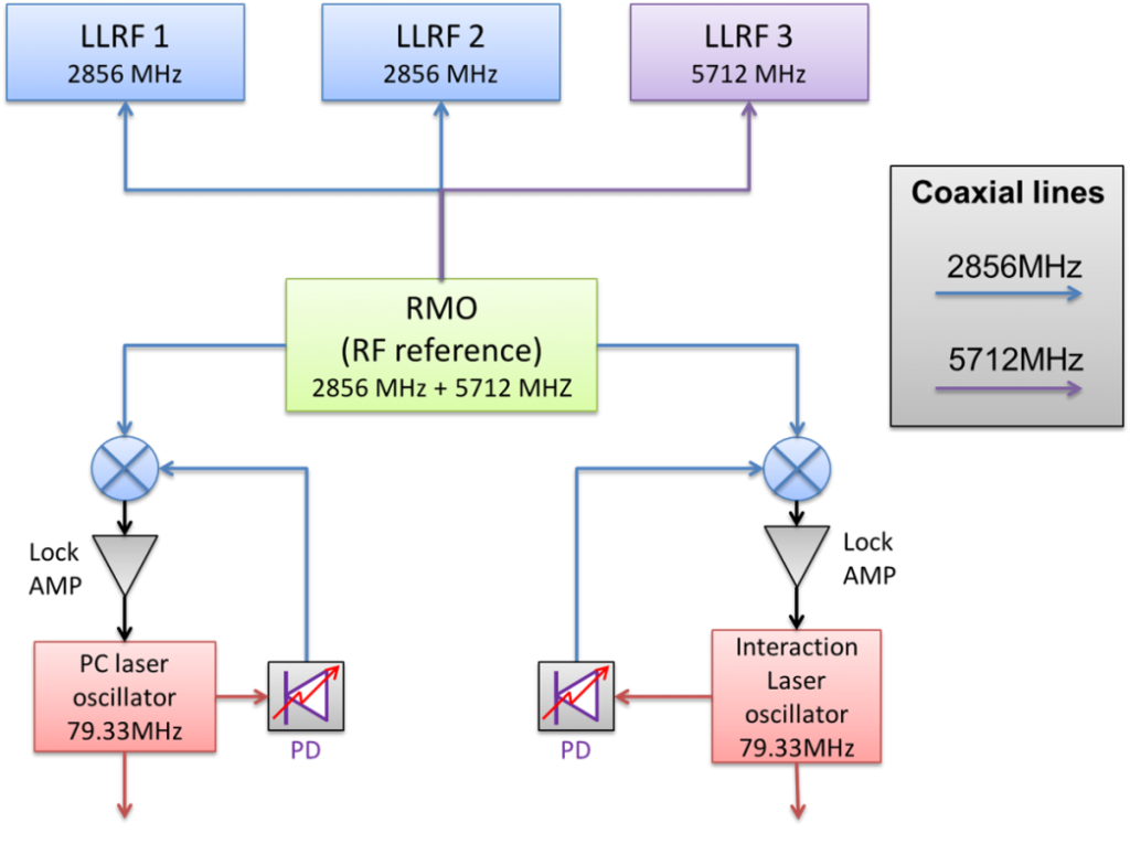
Figure 4. Layout of the SPARC_LAB synchronization system.
Presently, SPARC_LAB is running using an electrical architecture with good performances, but the transition to optical is under way. The simplified layout of the synchronization system is depicted in figure 4. The main oscillator generates both the S-band (2856 MHz) and C-band (5712 MHz) accelerating frequency. They are then distributed towards the clients using temperature compensated coaxial cables (not active stabilization is needed in this case). The system clients are:
- 2 S-band LLRF systems and power stations, that feeds the RF gun and the first two accelerating sections,
- 1 C-band LLRF and power station that feeds the third accelerating section,
- the photo-cathode laser oscillator, that is amplified and used to generate the electron bunch,
- the FLAME laser oscillator, that is used for interaction with electrons to generate X-rays and to study new acceleration techniques.
RF stations are directly fed, while the laser oscillators are tunable by means of piezo-controlled mirror and locked to the reference signal by PLL systems. Loop filters needs a dedicated design to reduce the residual incoherent jitter of the slave oscillators.
The system requirements depend on the experiment that is running in the facility. In particular, for seeded FEL and Thomson backscattering, the jitter between interaction lasers and electron bunch need to be <500 fs RMS. For Particle-driven Wake-Field Acceleration (PWFA), that needs the generation of multiple electron bunches inside the same RF bucket, a <100 fs time jitter between photo-cathode laser and RF accelerating is required. Last, but not least, for Laser-driven Wake-Field Acceleration (LWFA), that needs the interaction of high power laser pulse and electron bunch co-propagating inside a capillary filled with plasma, the allowed jitter between interaction laser and electrons is reduced to <10 fs.
Timing
Timing
Timing system is devoted to define the temporization of the event sequence necessary to realize an experiment (see figure 5).
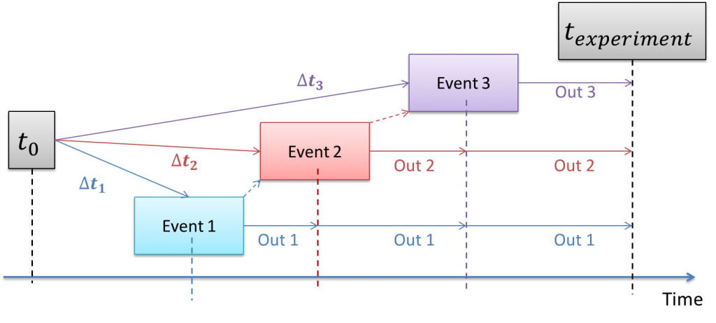
Figure 5. Timing system task
Digital delay signals in standard logic levels format (TTL, NIM, ECL, LVPECL, …) are typically used at the front-end level (input of the machine hardware). For this kind of signals the required time precision is in the 10ns to 10ps range.
In general, in mixed accelerator/laser experimental apparatus (photoinjectors, FEL, X-ray sources, advanced acceleration R&D), two kinds of signal distribution can be used, depending on the complexity and dimension of the machine.
- Electrical analog distribution: digital delay generators output is distributed by means of coaxial cables. They directly drive the final client. This system is simple, but client dependent from the beginning of the chain. Large links could suffer the attenuation/dispersion effects of coaxial cables.
- Optical digital encoded distribution: the signals are encoded with a standard digital protocol and packets are sent through optical fiber links. An event generator and many event receivers constitute the system. System is more complex, but it makes available more features (event tagging, smart management of triggers, …). Only the last connection toward the client is hardware dependent. Long links (hundreds of meters or some kilometers) can be installed without performance degradation.
A simplified layout of the SPARC_LAB timing system is given in figure 6. In this case the machine repetition rate is 10 Hz (one event every 100 ms) and a coaxial cable distribution is used. The trigger generation and delay is performed by means of commercial digital delay generators from SRS.
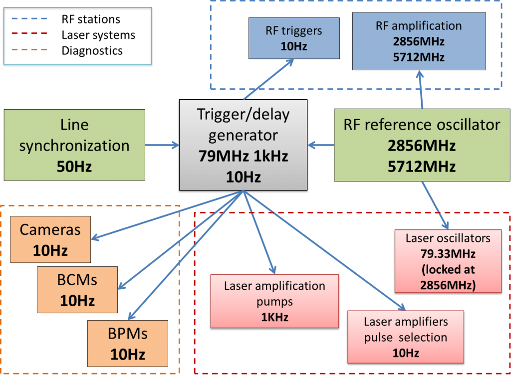
Figure 6. Layout of the SPARC_LAB timing system
Publication highlights:
- “Design, realization and test of C-band accelerating structures for the SPARC_LAB linac energy upgrade”, D. Alesini et al., Nucl. Instr. Meth. Phys. Res. A vol. 837 (2016) pag. 161, doi: 10.1016/j.nima.2016.09.010
- “Femtosecond timing-jitter between photo-cathode laser and ultra-short electron bunches by means of hybrid compression”, R. Pompili et al., New J. Phys. vol. 18 (2016) pag. 083033, doi: 10.1088/1367-2630/18/8/083033
- “Design of an X-band LLRF system for TEX test facility at LNF-INFN”, L. Piersanti et al., 12th Int. Particle Acc. Conf. proceeding (2021), doi: 10.18429/JACoW-IPAC2021-WEPAB301
- “Experimental and numerical characterization of timing jitter for short electron beams in a linear photo-injector”, G. Giannetti et al., Meas. Sci. Technol. vol. 35 (2) (2023) pag. 025015, doi: 10.1088/1361-6501/ad099c
- “Upgrade of the fast analogue intra-pulse phase feedback at SPARC_LAB” L. Piersanti et al., Proceedings of LLRF workshop (2023), doi: 10.48550/arXiv.2310.16458
- “Upgrade of the SPARC_LAB low level radiofrequency system”, L. Piersanti et al., Proceedings of 15th IPAC (2024), pag. THPS02, doi: 10.18429/JACoW-IPAC2024-THPS02
- “Design and Test of a Klystron Intra-Pulse Phase Feedback System for Electron Linear Accelerators”, L. Piersanti et al., Photonics, vol. 11 (2024), pag. 413 10.3390/photonics11050413
Contact person: M. Bellaveglia, marco.bellaveglia@lnf.infn.it Tel. (+39) 069403-2710